From last few days I was selecting parts for the open source tracking device and after testing /prototyping some of the parts I have build a prototype board in Eagle and have sent the same to fab house for manufacturing. It will take 10-15 days for prototype boards to arrive.
PCB design is a four layer board of size 4.5cms x 5.5cms. I have used stack based design, i.e. divided all the components into two boards and two board will be arranged one top of another. Both the boards will be soldered together using long male header pins. The Bottom board will have all the power supplies, battery management and microcontroller, the top board will have GPS, GSM, Indication LED’s, and buttons.
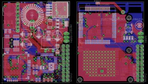
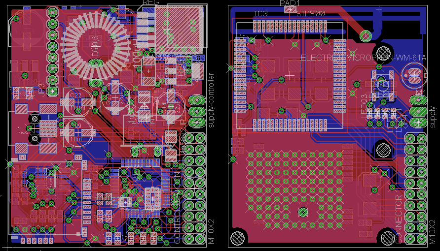
Board Layout in Eagle CAD
In the top board I have used microstrip antenna, I am not sure if it will work but since this is just a prototype board so no harm in checking it. If microstrip antenna works then we could bring cost a little lower. In addition to that I have placed a pad for external antenna mount, so if microstrip antenna doesn’t work I can solder antenna using a 50ohm coaxial cable.
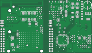
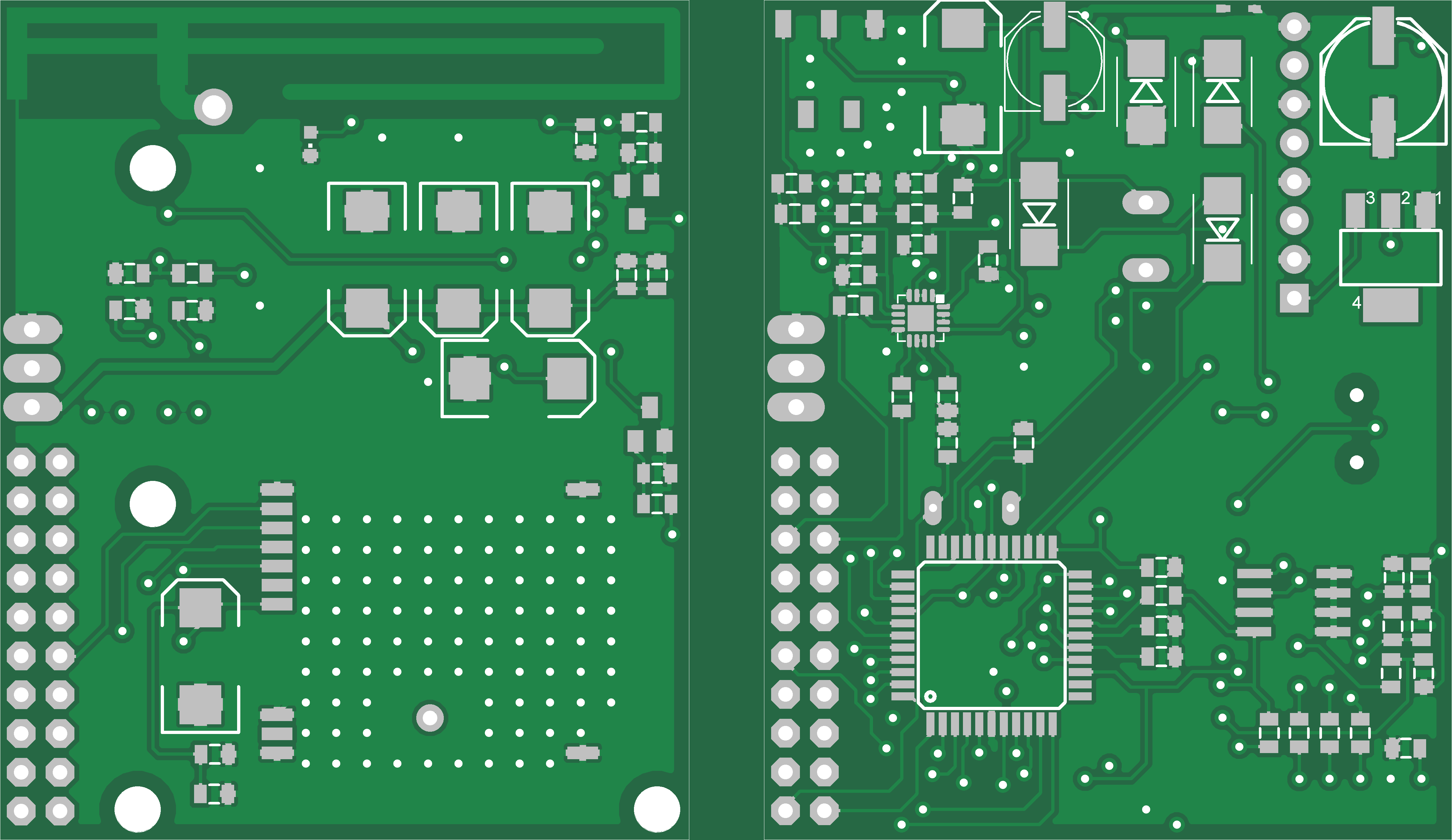
Bottom Side of Boards
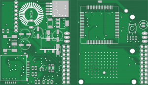
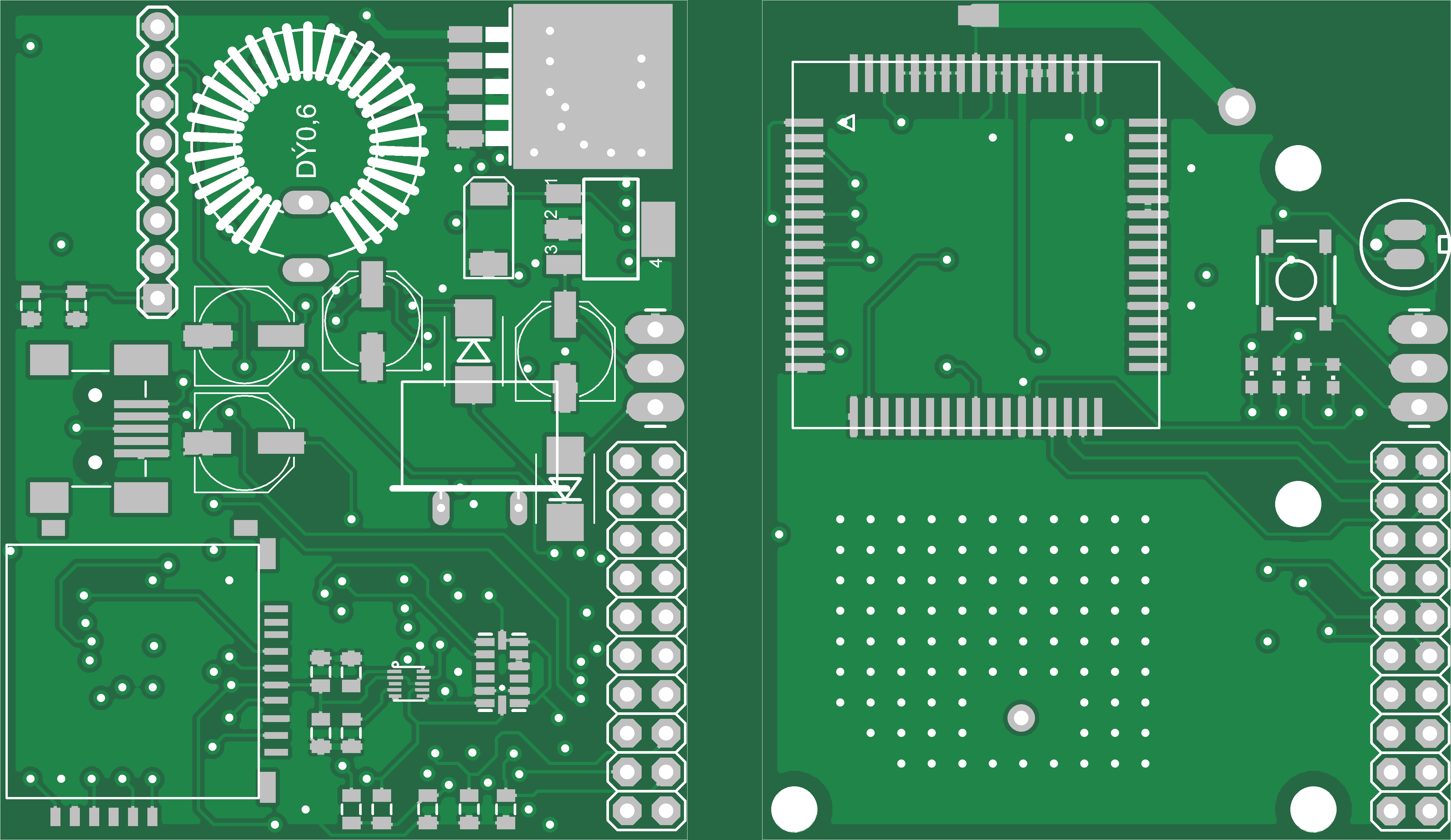
Top Side of Boards
The above two green PCB images are generated by google sketchup.
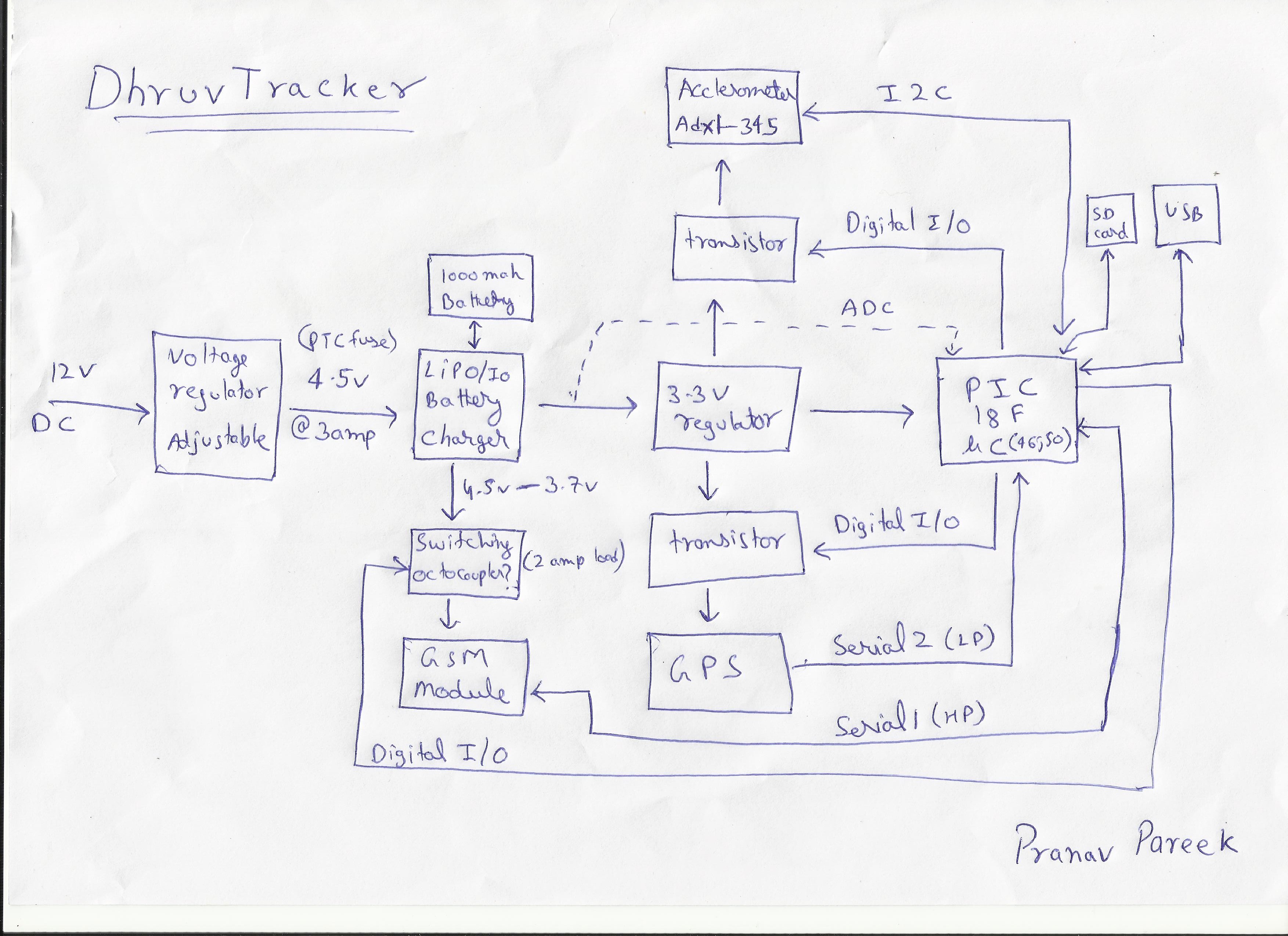
I’ll be releasing all the source cad, firmware, software files once I have built the tracker and completed all the testing. As per my last post these are the components I am using in the open source tracker design.
First up I have used LM2576 step-down (buck) switching regulator for main power supply. Because its cheap and can provide current up to 3amperes, which is more than enough for all power requirements on the tracker. The only downside of LM2576 is that it requires a big inductor of about 100uH which takes lots of PCB space. But I was able to fit it in the prototype board. This is a adjustable version of regulator, I have configured it to output about 4.5v because sim900 can work up to 4.8v but to fully charge lithium Ion battery we need at least 4.2v.
Next for battery management I have used BQ24075 from Texas Instruments, this little IC in QFN package can provide current up to 4 amps which is good since sim900 module requires 2amp of current when in transmitting mode. BQ24075 can automatically switch to battery if main power supply is removed. It has all the indications for charging and power good. It also has a short circuit detection feature which shuts down the output supply if short circuit is detected.
For powering sensors, microcontroller and external devices I have used two 3.3v regulators, MCP1826 and AMS1117. Both regulators can deliver up to 1000mAmps so I have used MCP1826 to power microcontroller, gps and on board sensors and AMS1117 to power any external 3.3v device.
Microcontroller used in this design will be PIC18F46J50 since it has two UARTs, one will be used by sim900 at higher priority and second one will be used by GPS at lower priority. It has 64KB of program memory, that will be sufficient for bootloader and application program. Enough RAM for parsing GPS NMEA strings and GSM responses. It works on 3.3v so it can be used directly with sensors eliminating any voltage level converters. It also have 5v tolerant pins that can be used with sim900 and external components. USB will be used for firmware updating and configuring the device.
ADXL345 accelerometer will work on i2c protocol, providing acceleration measurements, acceleration threshold can be defined so that if there is any big change in acceleration (during harsh break or collision) it can be detected and alert can be generated. Further I have also added MAG3110 magnetometer which is also connected to the i2c line. In absence of GPS, magnetometer and accelerometer can at least provide heading information. I also see a possibility of using magnetometer and accelerometer for dead reckoning feature, which is available in some high end tracking devices. Like if in long tunnel GPS signal is not available then with help of accelerometer a rough speed/distance can be calculated and using magnetometer heading can be obtained. Converging both data will result is new position coordinates. But if at all this can be done then I’ll work on this after testing and releasing all the source for tracking device. Other than accelerometer and magnetometer I have also used EEPROM, 24LC512 for storing user configurations. EEPROM will be connected to i2c line.
Once I get the prototype PCB’s i’ll mount all the components and will start writing the firmware. In the interim time I’ll work on web software design. As I make any progress I’ll post it here.
That’s all for now. If you have any comments or question which can improve this design please feel free to comment them below. Thank you for stopping by.